8:30 AM - 6:00 PM
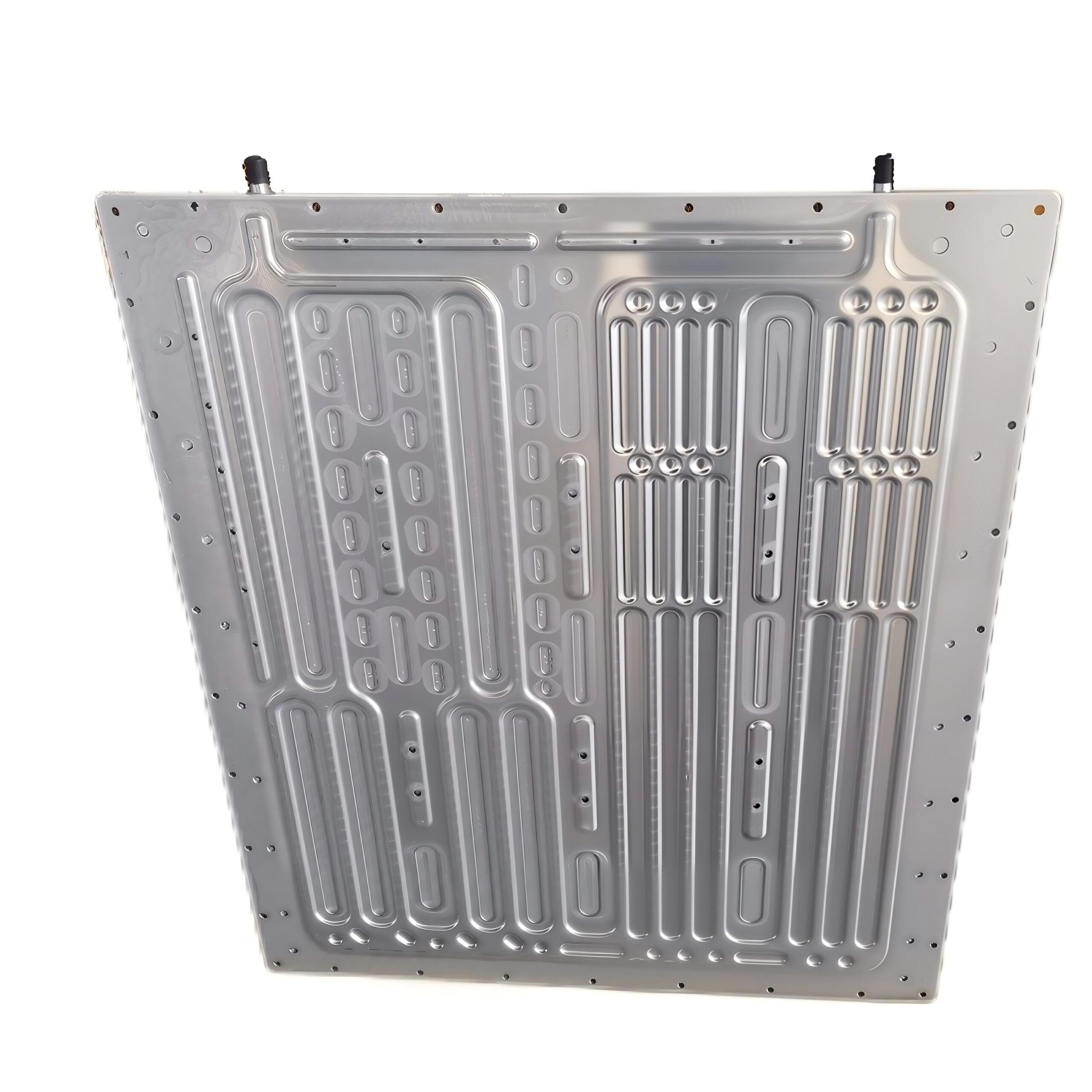
A stamped liquid cold plate (also known as stamped battery cooling plate or stamped brazed cold plate) is a high-performance thermal management component manufactured through precision metal stamping processes. It consists of a channel plate (lower plate) and base plate (upper plate) that are formed using stamping dies and then joined together through controlled atmosphere brazing (CAB) or vacuum brazing to create sealed internal cooling channels.
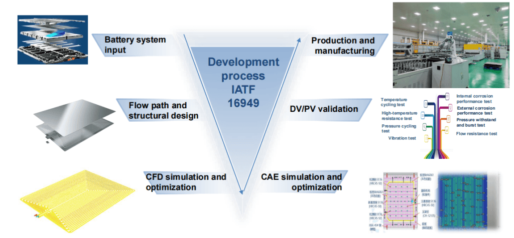
The stamped liquid cold plate manufacturing process combines precision aluminum stamping with controlled atmosphere brazing (CAB) or vacuum brazing to create high-efficiency cooling plates for electric vehicle batteries, power electronics, and high-performance computing. This production method offers the optimal balance of thermal performance, cost-effectiveness, and scalability for mass production.
As the EV market grows at 19.90% CAGR (2025-2034), stamped and brazed cold plates have become the industry standard for battery thermal management systems (BTMS), offering <3°C temperature uniformity, <8mm thickness, and 500-1500W cooling capacity per plate.
| Step | Description | Deliverables |
| 1.1 Requirements Analysis | Collect battery pack specs: cell type (prismatic/cylindrical/pouch), heat load, flow rate, pressure drop limits, space constraints | Technical specification document |
| 1.2 Flow Channel Design | Design serpentine, parallel, or topology-optimized channel patterns using CFD simulation | Channel geometry CAD files |
| 1.3 Thermal Simulation | CFD analysis (ANSYS Fluent, SolidWorks Flow) to optimize flow distribution, minimize temperature gradients | Thermal performance prediction report |
| 1.4 Stamping Die Design | Design progressive or compound dies for upper/lower plate forming | Die CAD models, DFM analysis |
| 1.5 Prototype Validation | Rapid prototyping (CNC machining) for initial thermal testing | Functional prototype samples |
Key Design Parameters:
– Channel Width: 5-15mm (optimized for flow rate and pressure drop)
– Channel Depth: 2-5mm (determines cooling capacity)
– Plate Thickness: 5-8mm final (after stamping)
– Flatness Requirement: <0.5mm (critical for thermal contact)
-Working Pressure: 3-4 bar (tested to >1MPa burst pressure)
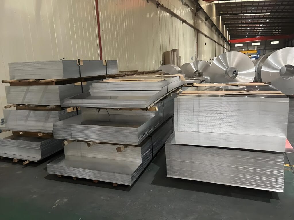
| Material | Specification | Application |
| Base Plate (Bottom) | Aluminum 3003-H14 or 6063-O | Structural support, coolant containment |
| Channel Plate (Top) | Aluminum 3003/4343 clad (4-10% Si filler metal) | Flow channels, brazing layer |
| Alternative Alloy | Aluminum 6061-T6 | Higher strength applications |
Material Preparation Steps:
1. Incoming Inspection: Verify alloy composition, thickness tolerance (±0.05mm), surface quality
2. Cutting: Shear or laser cut blanks to size (typical: 500×500mm to 2000×1500mm)
3. Surface Cleaning: Degreasing to remove oils, contaminants (critical for brazing quality)
4. Clad Layer Verification: Ensure 4343 cladding thickness (5-10% of total thickness) for proper brazing
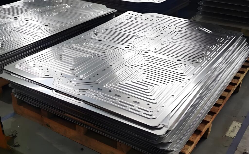
| Operation | Equipment | Parameters | Quality Check |
| Blanking | 2000-3000 ton hydraulic press | Cutting clearance 5-8% material thickness | Dimensional accuracy ±0.1mm |
| Channel Forming | Progressive stamping die | Punch speed 10-30 SPM, depth 2-5mm | Channel depth uniformity ±0.05mm |
| Piercing | Fine blanking or CNC | Hole diameter ±0.05mm for inlet/outlet | Burr height <0.05mm |
| Trimming | Laser cutting or trim die | Edge quality, flatness <0.5mm | Visual inspection, CMM sampling |
1. Stamping Die Specifications:
– Die Material: Cr12MoV or D2 tool steel, HRC 58-62
– Die Life: 300,000-500,000 strokes (standard), 1,000,000+ with carbide inserts
– Surface Finish: Ra <0.4μm on sealing surfaces
– Lubrication: Aluminum-compatible stamping oil (chlorine-free)
2. Key Stamping Quality Control Points:
– Channel Depth Consistency: Critical for flow uniformity (target: ±3% variation)
– Flatness Maintenance: Prevent warping during forming (use balanced die design)
– Surface Protection: Prevent scratches that could cause brazing defects
| Step | Process Details | Critical Parameters |
| 4.1 Degreasing | Alkaline or solvent cleaning to remove stamping oils, residues | pH 10-12, temperature 60-80°C, 5-10 minutes |
| 4.2 Acid Etching | Light chemical etching to remove oxide layer (optional) | 5-10% NaOH or HNO₃, 1-3 minutes |
| 4.3 Deionized Water Rinse | Multi-stage rinsing to remove all contaminants | Conductivity <50 μS/cm |
| 4.4 Drying | Hot air drying or oven drying | 100-120°C, complete moisture removal |
| 4.5 Flux Coating | Roll coating or spraying of NOCOLOK® flux (potassium fluoroaluminate) | Coating weight 3-5 g/m², uniform coverage |
Flux Coating Criticality:
– Purpose: Remove aluminum oxide during brazing, promote filler metal flow
– Coverage: 100% surface coverage, no bare spots
– Thickness: Excess flux causes corrosion, insufficient flux causes poor wetting
| Operation | Description | Quality Control |
| 5.1 Component Assembly | Stack top channel plate with bottom flat plate, align inlet/outlet holes | Visual alignment check |
| 5.2 Tox Riveting | Mechanical joining (toxing) to hold plates together before brazing | Joint strength verification |
| 5.3 Fixture Loading | Place assembly in brazing fixture with uniform pressure distribution | Fixture alignment verification |
| 5.4 Inlet/Outlet Installation | Install water nozzles/connectors (if pre-brazed installation) | Leak path verification |
Fixture Design Requirements:
– Uniform Pressure: Prevent warping during thermal cycling
– Thermal Expansion Compensation: Allow for aluminum expansion (23×10⁻⁶/°C)
– Gas Access: Ensure atmosphere circulation for CAB process
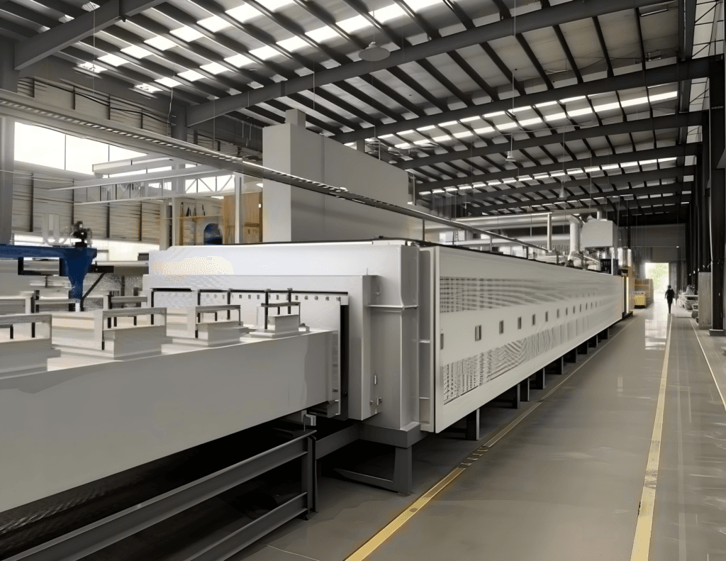
1. CAB Process Parameters
| Parameter | Specification | Control Tolerance |
| Furnace Type | Continuous tunnel furnace or batch furnace | N₂ atmosphere with <100 ppm O₂ |
| Heating Rate | 1-3°C/min (critical range: 450-580°C) | ±0.5°C/min |
| Brazing Temperature | 590-610°C (filler metal melting point ~580°C) | ±2°C |
| Peak Temperature Hold | 3-10 minutes at brazing temperature | Time ±30 seconds |
| Cooling Rate | 2-5°C/min (controlled cooling to 200°C) | Prevent thermal shock |
| Atmosphere | High-purity nitrogen (99.999%), dew point <-40°C | O₂ < 50 ppm |
| Total Cycle Time | 20-40 minutes (continuous furnace) | Process monitoring |
2. Alternative: Vacuum Brazing Process
| Parameter | Vacuum Brazing Specification | Advantage |
| Vacuum Level | 10⁻⁴ to 10⁻⁶ Pa (high vacuum) | No flux required, no oxidation |
| Heating Rate | 1-3°C/min | Uniform heating, minimal distortion |
| Brazing Temperature | 580-620°C | Precise temperature control |
| Hold Time | 10-30 minutes | Complete filler metal flow |
| Cooling | Controlled cooling with nitrogen backfill | Rapid, controlled solidification |
| Result | 100% leak-free, no flux residue | Highest reliability applications |
Brazing Quality Indicators:
– Joint Formation: Complete fillet formation at plate interfaces
– No Erosion: Base metal not dissolved by filler metal
– Void-Free: No unbrazed areas (ultrasonic inspection)
– Flatness Maintained: <0.5mm post-brazing warpage
| Step | Process | Purpose |
| 7.1 Degreasing/Flux Removal | Hot water rinse (CAB) or none (vacuum brazing) | Remove residual flux (CAB only) |
| 7.2 CNC Machining | Precision machining of mounting surfaces, connector threads | Dimensional accuracy ±0.05mm |
| 7.3 Drilling/Tapping | Inlet/outlet port machining, mounting hole creation | Interface specifications |
| 7.4 Surface Finishing | Deburring, edge breaking, surface cleaning | Safety and assembly readiness |
| 7.5 Surface Treatment | Anodization (Type II or III), chromate conversion, or epoxy coating | Corrosion protection, electrical insulation |
Surface Treatment Options:
– Clear Anodizing: 8-12μm thickness, corrosion resistance, paint adhesion
– Hard Anodizing: 25-50μm thickness, wear resistance for harsh environments
– Epoxy Coating: 0.2mm thickness for electrical insulation (battery applications)
– Chemical Film (Alodine): Conductive corrosion protection
| Test Type | Method | Acceptance Criteria | Equipment |
| 8.1 Visual Inspection | 100% visual check for brazing defects, surface quality | No cracks, no voids, complete fillets | Magnification 5-10x |
| 8.2 Dimensional Inspection | CMM measurement of critical dimensions | Flatness <0.5mm, hole positions ±0.1mm | Coordinate measuring machine |
| 8.3 Pressure Decay Test | Air pressure 3-4 bar, hold 5 minutes, measure pressure drop | ΔP < 5% (no leakage) | Pressure decay tester |
| 8.4 Helium Leak Test | Helium mass spectrometry (high sensitivity) | <1×10⁻⁹ mbar·L/s leak rate | Helium leak detector |
| 8.5 Thermal Performance Test | Flow test with heated fluid, measure temperature distribution | <3°C uniformity, target heat transfer coefficient | Thermal test rig |
| 8.6 Burst Pressure Test | Hydrostatic pressure to destruction | >3x working pressure (typically >9 bar) | Pressure test system |
| 8.7 Thermal Cycling | -40°C to 85°C, 100 cycles (sample testing) | No leaks, no degradation | Thermal cycling chamber |
Testing Standards Compliance:
– Automotive: IATF 16949, ISO 6469 (EV safety)
– Pressure Equipment: PED 2014/68/EU, ASME VIII
– Environmental: IEC 60068-2-14 (thermal cycling), IEC 60068-2-64 (vibration)
| Step | Description | Quality Check |
| 9.1 Accessory Installation | Install quick connectors, gaskets, mounting hardware | Torque verification, compatibility check |
| 9.2 Final Cleaning | Remove machining debris, protective film application | Cleanliness verification |
| 9.3 Protective Packaging | VCI film, EPE foam, wooden pallet (ISPM-15) | Moisture protection, impact protection |
| 9.4 Documentation | CoC, test reports, material certificates, assembly drawings | Complete traceability |
| 9.5 Shipping | FOB, CIF, or DDP delivery per customer requirement | Logistics coordination |
| Process | Stamped + CAB Brazing | Stamped + Vacuum Brazing | Extrusion + Machining | Friction Stir Welding (FSW) |
| Initial Investment | Medium (stamping dies) | High (vacuum furnace) | Low (extrusion die) | High (FSW equipment) |
| Unit Cost (High Volume) | Very Low | Low | Low | Medium |
| Production Rate | Very High (60-120 SPM) | High (batch process) | Medium | Medium |
| Design Flexibility | High (complex channels) | High (complex channels) | Limited (straight channels) | Medium |
| Temperature Uniformity | <3°C | <3°C | <5°C | <4°C |
| Leak Reliability | Excellent (99.5%+ yield) | Superior (99.9%+ yield) | Good | Superior (hermetic) |
| Best For | High-volume EV batteries | Premium EV, aerospace | Cylindrical cells, cost-sensitive | Heavy-duty, large plates |
| Max Plate Size | 2000×1500mm | 1500×1000mm | 500×500mm | 1500×1000mm |
| Defect | Cause | Prevention | Detection |
| Brazing Void/Unbrazed Area | Insufficient flux, poor fit-up, temperature non-uniformity | 100% flux coverage, fixture pressure control, furnace profiling | X-ray, ultrasonic, helium leak test |
| Excessive Warpage | Uneven heating/cooling, insufficient fixture constraint | Optimized heating rate, improved fixture design | CMM flatness measurement |
| Filler Metal Erosion | Overheating, excessive hold time | Strict temperature control, time monitoring | Metallographic cross-section |
| Surface Oxidation (CAB) | Insufficient nitrogen purity, air ingress | O₂ monitoring, furnace sealing maintenance | Visual inspection |
| Channel Collapse | Excessive stamping force, thin material | Die design optimization, material thickness control | Visual, dimensional inspection |
| Leakage at Joints | Poor brazing, thermal stress cracks | Optimized brazing parameters, thermal expansion design | Pressure decay, helium test |
– AI-Generated Geometry: Non-intuitive flow paths that improve heat transfer by 25.7% and reduce pressure drop by 30.6%
– Generative Design: Algorithms create optimal material distribution for thermal and structural requirements
– Manufacturing: Stamping dies produced via CNC or EDM to match optimized geometries
– Real-Time Monitoring: Temperature, pressure, and atmosphere sensors throughout production
– Predictive Quality: Machine learning models predict brazing outcomes from process parameters
– Traceability: Blockchain or database tracking of every plate from material to shipment
– Hybrid Approach: 3D-printed internal fins combined with stamped base plates
– Rapid Prototyping: Direct metal printing for prototype validation before die investment
1. Q: What is a liquid cold plate and how does it work?
A: A liquid cold plat is a heat exchanger that transfers heat from electronic components or batteries to a liquid coolant. It consists of a thermally conductive plate (aluminum or copper) with internal flow channels. Heat conducts from the heat source into the plate, then convects to the flowing coolant, which carries heat away to a remote radiator or heat exchanger. Cold plates achieve 10-50x better heat transfer than air cooling, enabling higher power densities and precise temperature control.
2. Q: How do I choose between stamped/brazed, extruded, and FSW cold plates?
A: Stamped/brazed: Best for large-area EV battery cooling (prismatic cells), complex channel geometries, and high-volume production. Extruded: Cost-effective for cylindrical cell cooling (straight channels), moderate performance requirements. FSW: Ideal for high-reliability applications (aerospace, military), excellent leak tightness, and thick plates requiring high structural integrity. We help you select based on thermal requirements, volume, budget, and reliability needs.
3. Q: What coolant should I use with your liquid cold plates?
A: Water-ethylene glycol (50/50 mix) is standard for most applications, offering freeze protection to -37°C and good thermal conductivity. Deionized water provides best thermal performance in controlled environments. Dielectric fluids (PAO, fluorocarbons) are required for direct contact with electronics. Refrigerants (R1234yf, CO₂) enable two-phase cooling for extreme heat fluxes. We provide material compatibility guidance to prevent corrosion.
4. Q: What is the stamped liquid cold plate manufacturing process?
A: The stamped liquid cold plate manufacturing process involves: (1) Precision stamping of aluminum plates (3003/4343 clad) using 2000-3000 ton presses to create flow channels; (2) Surface preparation including degreasing and flux coating; (3) Controlled atmosphere brazing (CAB) at 590-610°C in nitrogen atmosphere or vacuum brazing at 10⁻⁴-10⁻⁶ Pa; (4) CNC machining of interfaces; (5) Quality testing including helium leak detection (<1×10⁻⁹ mbar·L/s) and thermal validation.
5. Q: What temperature is used for brazing cold plates?
A: Cold plates are typically brazed at 590-610°C for aluminum alloys. The filler metal (4343 alloy with 7.5-10.5% Si) melts at ~580°C, requiring precise temperature control with ±2°C tolerance. Heating rate should be 1-3°C/min to prevent thermal shock, with 3-10 minute hold time at peak temperature for complete filler metal flow.
6. Q: How are cold plates tested for leaks?
A: Cold plates undergo three levels of leak testing: (1) Pressure decay test at 3-4 bar air pressure with <5% pressure drop over 5 minutes; (2) Helium mass spectrometry for high-sensitivity detection (<1×10⁻⁹ mbar·L/s leak rate); (3) Thermal cycling test from -40°C to 85°C for 100 cycles to validate long-term sealing integrity.
7. Q: How do you ensure temperature uniformity across the cold plate surface?
A: We achieve uniformity through four strategies: (1) Topology-optimized channel design that directs more flow to high-heat zones; (2) Parallel flow configurations ensuring identical inlet conditions; (3) Counter-flow arrangements balancing temperature gradients; (4) Multi-zone cooling with independent flow control for highly non-uniform heat loads. Our target is < 3°C variation for EV batteries, with < 2°C achievable for premium applications.
Contact our engineering team for a detailed quotation within 24 hours.
WhatsApp us
Disclaimer: We promise not to automatically push advertising emails for you.

Condition:New
Fin Material:Copper
Speed:100 M/min
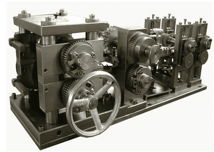
Working Principle:Fin Rolling Mechanism
We will contact you within 4 hours, please note that the email suffix is “@radiatormachine.com”.

Condition:New
Workpiece specification:as per drawing’s requirement
Workpiece length:100-1000mm
Production capacity:180 pcs/hour
Drive mode:Servo+Hydraulic+Pneumatic
We will contact you within 4 hours, please note that the email suffix is “@dagmachinery“.

Height Of Brazing Furnace:250mm
Width Of Brazing Furnace:1000mm
Mesh Belt Operating Surface Height:900mm
Length Of Brazing Furnace:6000mm
Working Station Size:1000mm×250mm
Speed:150~600mm/min
We will contact you within 4 hours, please note that the email suffix is “@dagmachinery“.

Condition:New
Fin Making Machine :280m/min
coil inner diameter:300mm
Fin cutting frequency: max 80 times/min;
We will contact you within 4 hours, please note that the email suffix is “@dagmachinery“.

Pipe effective length: 200-650mm
Slot forming time: 20 seconds per pipe
Hydraulic system working pressure: 8-21Mpa
pneumatic system working pressure: 0.5-0.8Mpa
overall dimension: 2500mm×2100mm×2750mm
We will contact you within 4 hours, please note that the email suffix is “@dagmachinery“.
Core Components:PLC, Motor
Condition:New
Height Tolerance:+0.03mm, – 0.01mm
Fin Width:8~200mm (Customized)
We will contact you within 4 hours, please note that the email suffix is “@dagmachinery“.

Core Components:PLC, Motor
Condition:New
Height Tolerance:+0.03mm, – 0.01mm
Fin Width:8~200mm (Customized)
We will contact you within 4 hours, please note that the email suffix is “@dagmachinery“.

Core Height:350-780mm (Customized)
Core Thickness:16~48mm (Customized)
Clearance Between Fin & Header Plates:2mm (1.0mm)
Built Core Width Error:±1.5mm
We will contact you within 4 hours, please note that the email suffix is “@dagmachinery“.

Machine Weight:About 2100kg
Radiator Core Height:100-800mm
Suitable Teeth Pitch:Adjustable, Default 10mm
Clinching Speed:1-20 Times Per Minute
We will contact you within 4 hours, please note that the email suffix is “@dagmachinery“.

Working speed:0-100m/min stepless control
Fin height: 8±0.05mm
Voltage, Power:380V/50Hz,4.5kw
Protective Shield:Can Be Customized
Programmable:Yes
We will contact you within 4 hours, please note that the email suffix is “@dagmachinery“.

Conditions:NEW
Fin & Tube Collocating Time:1 Second Per Collocation
Voltage, Power:380V 50Hz ≤13Kw
Applicable Core:Radiator Core, Condenser Core
We will contact you within 4 hours, please note that the email suffix is “@dagmachinery“.